To drive the wind generator, a rotor-type turbine with a vertical axis of rotation is manufactured. This type of rotor is very strong and durable, has a relatively low rotation speed and can easily be made at home, without the hassle of an airfoil and other problems associated with making a rotor for a horizontal axis wind turbine. Moreover, such a turbine operates almost silently, regardless of which way the wind blows. The work is practically independent of turbulence and frequent changes in wind strength and direction. The turbine is characterized by high starting torques and operation at relatively low speeds. The efficiency of this turbine is small, but it is enough to power low-power devices; everything is paid off by the simplicity and reliability of the design.
Electric generator
A modified compact car starter with permanent magnets is used as a generator. Generator output data: alternating current power 1.0...6.5 W (depending on wind speed).
An option for converting a starter into a generator is described in the article:

Manufacturing of a wind turbine
This wind turbine costs almost nothing and is easy to make.
The turbine design consists of two or more half-cylinders mounted on a vertical shaft. The rotor rotates due to the different wind resistance of each of the blades, turned to the wind with different curvature. The efficiency of the rotor is increased somewhat by the central gap between the blades, since some air additionally acts on the second blade as it exits the first.
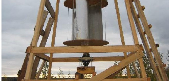
The generator is fixed to the rack by the output shaft, through which the wire with the resulting current comes out. This design eliminates the sliding contact for current collection. The turbine rotor is installed on the generator housing and fixed to the free ends of the mounting studs.
A disk with a diameter of 280...330 mm or a square plate inscribed in this diameter is cut out of an aluminum sheet 1.5 mm thick.
Relative to the center of the disk, five holes are marked and drilled (one in the center and 4 in the corners of the plate) for installing the blades and two holes (symmetrical to the central one) for attaching the turbine to the generator.
Small aluminum corners, 1.0...1.5 mm thick, are installed in the holes located in the corners of the plate to secure the blades.


We will make turbine blades from a tin can with a diameter of 160 mm and a height of 160 mm. The can is cut in half along its axis, resulting in two identical blades. After the cut, the edges of the can, at a width of 3...5 mm, are bent 180 degrees and crimped to strengthen the edge and eliminate sharp cutting edges.


Both turbine blades, on the side of the open part of the can, are connected to each other by a U-shaped jumper with a hole in the middle. The bridge creates a 32mm wide gap between the central part of the blades to improve rotor efficiency.

On the opposite side of the can (at the bottom), the blades are connected to each other by a bridge of minimal length. In this case, a gap of 32 mm wide is maintained along the entire length of the blade.

The assembled block of blades is installed and attached to the disk at three points - at the central hole of the jumper and the previously installed aluminum corners. The turbine blades are fixed to the plate strictly one against the other.
To connect all the parts, you can use rivets, self-tapping screws, M3 or M4 screw connections, corners, or other methods.

The generator is installed into the holes on the other side of the disk and secured with nuts to the free ends of the mounting studs.

For reliable self-starting of the wind generator, it is necessary to add a second similar tier of blades to the turbine. In this case, the blades of the second tier are shifted along the axis relative to the blades of the first tier at an angle of 90 degrees. The result is a four-blade rotor. This ensures that there is always at least one blade that is able to catch the wind and give the turbine a boost to spin.
To reduce the size of the wind generator, a second tier of turbine blades can be fabricated and secured around the generator. We will make two blades 100 mm wide (the height of the generator), 240 mm long (similar to the length of the first tier blade) from an aluminum sheet 1.0 mm thick. We bend the blades along a radius of 80 mm, similarly to the blades of the first tier.

Each blade of the second (lower) tier is secured with two corners.
One is installed in a free hole on the periphery of the disk, similar to the mounting of the upper tier blades, but shifted by an angle of 90 degrees. The second corner is attached to the stud of the generator being installed. In the photo, for clarity of fastening the blades of the lower tier, the generator has been removed.
Issues of energy independence worry the minds of not only leaders of states and enterprises, but also individual citizens and owners of private houses. With the increase in monopoly and tariffs by electricity producers, people are looking for efficient alternative sources nutrition. One such source is a wind generator.
Main elements in a wind generator system
There are many models, options from different manufacturers, but as practical experience shows, they are not always affordable and of quality for a wide range of consumers. If you have information, certain knowledge of electrical engineering and practical skills, you can make a wind generator yourself.
Operating principle and main elements
The operation of a homemade wind generator is no different from industrial models; the operating principles are the same. Wind energy is converted into mechanical energy rotation of the generator rotor, which produces electricity.
Main design elements (Fig. above):
- propeller with blades;
- a rotation shaft through which torque is transmitted to the generator rotor;
- generator;
- design for mounting the generator at the installation site;
- if necessary, to increase the rotor speed, a gearbox or belt drive can be installed between the shaft with the propeller and the generator shaft;
- for conversion alternating current generator to DC converter is used, a rectifier diode bridge, the current from which is supplied to recharge the battery;
- a battery from which electricity is supplied through the inverter to the load;
- inverter converts D.C. batteries with a voltage of 12 V or 24 V AC with a voltage of 220 V.
The designs of propellers, generators, gearboxes and other elements may differ, have different characteristics, and additional devices, but the system is always based on the listed components.
Do-it-yourself selection and production
According to the design, there are two types of axis that rotate the generator rotor:
- generators with a horizontal axis of rotation;

Generator with horizontal axis of rotation
- generators with a vertical axis of rotation.

Rotary wind generator with vertical axis of rotation
Horizontal axes of rotation
Each design has its own advantages and disadvantages. The most common option is with a horizontal axis. These models have a high efficiency of converting wind energy into rotational movements of the axis, but there are certain difficulties in calculating and making the blades yourself. The usual flat blade shape, which was used on ancient windmills, ineffective.
To use maximum wind energy when rotating the axis, the blades must have a wing-shaped shape. On airplanes, the shape of the wing, due to the force of the headwind, provides lifting flows. In the case under consideration, the forces of these flows will be directed to rotate the generator shaft. Propellers can be with two, three, or big amount blades, the most common designs are those with three blades. This is quite enough to provide the required rotation speed.
Wind generators with a horizontal axis of rotation must be constantly turned by the plane of the propeller towards the front of the oncoming wind flow. To do this, it is necessary to use a weathervane-type tail unit, which, under the influence of the wind, like a sail, turns the entire structure with a propeller towards the headwind.
Vertical axes of rotation
The main disadvantage of this option is low efficiency, but this is compensated by a simpler design, which does not require the manufacture of additional elements to turn the blades towards the wind. The vertical arrangement of the axis and blades allows you to use wind energy for rotation from any direction; this design is easier to make with your own hands. The shaft rotates more stably, without sudden jumps in speed.
The average annual wind speeds on the territory of Russia are not the same. Most favorable conditions for the operation of wind generators – 6-10 m/s. There are few such areas; winds of 4-6 m/s generally prevail. To increase the rotation speed, it is necessary to use gearboxes and take into account the height and wind rose in the area where the generator is installed.
An example of wind generator manufacturing
A variant with a vertical axis of rotation is being considered.
DIY wind turbine
The easiest option for producing blades is to use a 50-200 liter metal barrel. Depending on the number of blades required, the barrel is sawn with a grinder from top to bottom into 4 or 3 equal parts.

Vertical blades from a metal barrel
You can simply use sheets of galvanized roofing iron, which can be easily cut into the desired shape with your own hands using metal scissors.

Vertical blades made of sheet iron
Subsequently, the blades are attached to the top of the rotation axis. The basis for their fastening can be wooden disks made of six-layer plywood.
It is safer to use a metal frame made of a rectangular profile, to which the blades are bolted.

Example of placement of vertical blades

An example of attaching blades to a platform
The frame or disks are rigidly attached to the rotation axis; the axis itself is inserted into couplings with bearings, which are securely installed in the frame of the tower or roof of the building on which the generator is located.
Installing an axle with blades on a tower

A visual representation of the installation of a vertical axis of rotation on the roof of a building
- Turbine with vertical blades.
- Axle stabilization platform with double-row ball bearing.
- Steel cable braces Ø 5mm.
- Vertical axis, steel pipe Ø 40-50mm, wall thickness not less than 2 mm.
- Rotation speed control lever.
- The blades of the aerodynamic regulator are made of plywood or plastic 3-4 mm thick.
- Rods that regulate the speed of rotation and the number of revolutions.
- A load whose weight sets the speed of rotation.
- Vertical axis pulley for belt drive, widely used bicycle wheel rim, without tube and tire.
- Support bearing.
- Pulley on the generator rotor axis.
A pulley for a belt drive or gears for a gearbox is attached to the lower end of the axle; this is necessary to increase the rotation speed of the rotor. Practice shows that at a wind speed of 5 m/s, the rotation of the shaft with horizontal blades from the barrel will be no more than 100 rpm. At a wind speed of 8-10 m/s, rotation reaches up to 200 m/s. This is very little for the generator to produce required power to charge the battery.
A 1:10 ratio gearbox allows you to achieve the required rotation speed.

Installing Belt Pulleys
Low speed generator
The easiest way to convert mechanical rotational energy into electricity is to use car generators. But ordinary generators from passenger cars They are not recommended for windmills due to the presence of brushes in their design. Graphite brushes remove the current induced on the rotor; during operation, they wear out and require replacement. In addition, such generators are high-speed; to generate a voltage of 14 V with a current of up to 50A, 2000 or more revolutions are required.
More efficient generators for wind turbines from tractors and buses G.964.3701 with magnetic excitation of windings. They do not have brushes and operate at lower speeds. Generator G288A.3701 has three phases and is used for power supply Vehicle together with the battery. It has good characteristics for use in wind turbine systems:
- produces a voltage of 28 V;
- built-in rectifier produces direct current up to 47 A;
- output power up to 1.3 kW;
- on Idling rotation 1200 rpm;
- with a current load of 30A, 2100 rpm is required.
The generator has suitable dimensions and weight:
- total weight 10 kg;
- diameter 174 mm;
- length 230 mm.

Generator from MAZ - 24V
Generators of this type are used in KAMAZ, Ural, KRAZ, MAZ vehicles with engines from the Yaroslavl plant YaMZ 236, 238, 841, 842 and ZMZ 73. In order to save money, you can buy a used generator at dismantling points. To generate more electrical power at low speeds, you can make a generator with your own hands using neodymium magnets, but this is a separate topic and requires a more detailed description.
Assembly sequence
- First of all, a tower or generator mounting structure is installed on the roof of the building. The vertical axis is attached to bushings with bearings, and the blades are installed.
- After installing the axis with the blades, a pulley for the belt drive is fixed on the lower part.
- At the level of the axle pulley, a generator with a pulley for the belt on the rotor shaft is attached to a specially prepared platform. The generator pulleys and axles with blades must be installed at the same level.
The diameter of the pulley on the axle should be approximately 10 times larger than the diameter of the pulley on the generator shaft. Based on the conditions that the estimated wind speed is approximately 10 m/s, the axis rotation speed will be up to 200 rpm.
The formula used is:
Wr = Wos x Dosd, where
- Wr – generator pulley rotation speed;
- Dos – pulley diameter on the vertical axis;
- d – diameter of the pulley on the generator rotor shaft;
- Wos is the rotation speed of the vertical axis pulley.
Wr = 200 rpm x 500mm/50 mm = 2000 rpm - sufficient rotation speed for the generator of the selected type to produce the required power.
- The belt is tensioned; to do this, there must be slots in the generator mounting platform, like on a car mounting.
- The output wires of the generator are connected to the battery terminals.
These generators have built-in rectifiers, the output is direct current, so the positive red wire is attached to the “+” terminal, and the negative wire is attached to the “minus” terminal.
- The 24V/220V inverter input is connected to the battery, also observing the polarities.
- The inverter output is connected to the circuit with the load.
Video. DIY wind generator.
Having necessary materials, practical skills in plumbing, using ready-made automobile generators with magnetic excitation of the windings, the wind generator is easy to install with your own hands. To manufacture a higher-power generator using neodymium magnets, more in-depth knowledge in electrical engineering and skills in assembling electrical equipment will be required. This is one of the most simple ways assemble a wind generator with your own hands.
An important condition for the full functioning of the stove is normal draft, which will help remove combustion products. This indicator is greatly influenced by the diameter of the chimney. If it is of small cross-section, then combustion products will not be able to escape outside and will begin to accumulate inside the home. If you use a wide chimney pipe, cold air flows will prevent burnt substances from rising. All these and other nuances can be compensated for by a traction amplifier, which you can actually make yourself
Traction Options
There are several types of devices that can increase the outgoing air flow. Among them the most popular are:- Deflector . Structurally, it increases the diameter of the chimney outlet.
- . A device that is installed on the top of the chimney (turns against the wind), protecting its mouth from dust and protecting it from various precipitation.
- Smoke fans . Most often they are installed on a fireplace chimney with a small cross section. They can be turned on when there is not enough natural wind flow.
- Rotary turbines . Such devices are installed on the head of the pipe to provide free access to the wind. They are best suited for gas boilers.
But the simplest and no less effective is to lengthen the chimney pipe. At the same time, the difference in air pressure increases and the thrust increases. Typically, the chimney pipe is 5 meters high (this distance includes the vertical section of the chimney without taking into account elbows, slopes and narrowings).
If the roof has a sharp slope or large objects are located near it, then these circumstances worsen the draft, which will help overcome the increase in the length of the chimney. But when strongly long pipe There may be heat loss, which will not be used to heat the home, but to heat the cold street air. To prevent this from happening, the furnace is equipped with special dampers that regulate the amount of exhaust gas.
DIY deflector installation
The device optimizes air removal, being a reflective device. It won’t be difficult to do it yourself – just arm yourself necessary tool and purchase sheets of galvanized metal. Their thickness should be no more than 1 mm.The simpler the design of the deflector, the more accurate the drawings will be and the more efficient the device. No need to come up with an intricate shape. The most elementary diagram is taken as an example. Dimension D is the diameter of the pipe with a small gap so that the deflector can be securely fixed to it. Di – twice the cross-section of the chimney.

Required tools:
- roulette;
- electric drill;
- clamps;
- hammer;
- square;
- metal scissors, hacksaw or grinder;
- riveter;
- heat-resistant mastic;
- self-tapping screws;
- parts for fastenings.
- Mark the dimensions of the workpieces on the sheet of metal. Cut them out.
- Roll the future body of the nozzle into a ring and fasten its edges with rivets or self-tapping screws.
- Assemble the cone to connect to the chimney in the same way.
- Combine both products. For better sealing, treat their joints with mastic.
- Build a metal umbrella and secure it on top of the deflector with pins or rivets if it is made on legs.
- Strengthen the stability of the structure by using clamps.
Weather vane to increase traction
This amplifier, unlike the previous one, can rotate around the chimney. The principle of operation of the device is its response to air currents, as a result of which the traction amplifier takes the appropriate direction from any wind blow. Air is blown into special grilles, which creates a constant vacuum in the pipe.
The demonstrated product can operate in any weather conditions. It reacts even to a slight breeze. The invented device improves the efficiency of the combustion boiler by approximately 20%. If you install it on a pipe, you will not need to make the chimney very long; you can shorten the part visible above the roof.
The weather vane is an exhaust product for the ventilation system, so it can be used for apartment buildings and private houses. It has gained particular popularity when installing gas boilers. The device not only increases draft, but also prevents the boiler from fading.
Electric fans
Powerful fans that are used for fireplaces and wood-burning stoves. They are designed to work in hot environments where there is a lot of ash and other combustion products.
The body of such devices is made of galvanized steel with a specially applied polymer coating, which provides protection from aggressive environments. It has a protective grille that prevents various large and medium-sized objects from entering the air duct.
The ventilation device operates from a single-phase motor, which can ensure uninterrupted operation of the system in any weather. Although it is protected from the flow of hot air, for safety reasons it is placed outside the zone of its movement. It has ventilation holes and a special wheel that prevents the adhesion of soot and dust.
This ventilated system is fully automated. It has built-in temperature sensors, as well as their analogues, that regulate the force of air flow. They respond to deviations in the operation of the electric motor and create optimal traction for the device.
Their operating principle is similar to a deflector - they are also located at the top of the pipe and use wind energy. The nozzle on which the grilles with wings are located rotates in one direction, regardless of the direction of the wind. Due to its movement, it creates the necessary air vacuum. The design of the device resembles a dome and is able to protect the chimney from debris and precipitation. It is intended for gas boilers and ventilation ducts. Not recommended for solid fuel boilers and fireplaces.

In calm weather, this amplifier does not work, but in the summer, when the boiler is not functioning, it can create a very strong draft, which is often unnecessary.
Description and operating diagram of the traction amplifier (video)
In the next video, experts will talk about the amplifier, as well as its operating circuit. At the same time, they will indicate the advantages of this method of removing combustion products.The design of the smoke exhaust duct and the type of boiler that heats the home will help decide which of the proposed devices to choose. You can resort to them if you cannot increase the length of the pipe.
To paraphrase a catchphrase from a famous film, we can say that ventilation is a delicate matter; too many factors influence the stable operation of the exhaust pipe. It’s rare that someone manages to build a ventilation system in a house with a small pipe that takes up minimal space on the roof and at the same time has high performance. Over time, as the ventilation ducts become dusty and overgrown, the performance and efficiency of the ventilation system noticeably decreases, so it is necessary to install a deflector on the ventilation pipe. Best models capable of increasing productivity up to 20% of the original thrust value.
What is a deflector?
Today, a cylindrical, cone-shaped or rounded deflector body can be seen on the roofs of private houses. In essence, the deflector is an aerodynamic nozzle designed to create additional vacuum at the cut of the ventilation pipe. As a result, the pressure difference above the pipe and inside the room increases, the draft and performance of the ventilation system increases.
Structurally, any deflector consists of three units:
- Housings with fastenings that provide reliable and durable installation at the cut of the ventilation pipe;
- Air flow capture systems consisting of several fixed airfoils or a rotating element, as in the case of turbine deflectors;
- A cap or protective cover that covers the pipe section from the penetration of rain, snow, curious birds, insects, mice and other living creatures.
For your information! A remarkable property of the deflector is its absolute autonomy. The device, which provides an additional increase in thrust by almost 10-20%, operates without external sources of electrical or thermal energy.
To operate, the ventilation deflector requires one condition - a constant, stable horizontal wind flow, preferably in one direction. In conditions of constant air flow, the deflector nozzle allows you to reduce the height of the ventilation pipe on the roof by almost half. When there is no wind, the deflector practically does not work.

Increasing draft due to compression of additional air flow is also used in chimneys and blowdowns, when it is necessary to quickly remove combustion products, smoke, fumes, and soot from a room or combustion chamber. The deflector helps to sharply intensify combustion. For example, in the era of steam locomotives, an improvised booster was used: in order to sharply increase the power of a steam engine, steam from the boiler was released through chimney outward, which increased the combustion intensity and engine power by almost 70%.

Design and principle of operation of the ventilation pipe deflector
The design and operating principle of the deflector amplifier are based on the well-known physical phenomenon drop in static pressure in the flow of air or water. A simplified design and operating diagram of the deflector are shown in the drawing and figure.

The basis of the design is a simplified aerodynamic profile, as a rule, these are two vertically located cones or ridges, with their apices directed towards each other. The air flow, flowing around a cone-shaped or spherical profile, is compressed and accelerated under the influence of dynamic pressure, at least twice.
As a result, the air pressure at the end of the ventilation pipe drops, which ensures an increase in ventilation performance. The design cannot be called absolutely silent. When designing the dimensions and characteristics of the deflector, developers use average values of horizontal air flows. In practice, wind speed can exceed 15 - 20 m/s, which leads to air vibrations in the form of a hum and high-frequency whistle. To avoid making the deflector noisy, most modern models are manufactured in the form of numerous sectors and straightening grids.
The deflector should not be confused with an electric exhaust fan installed at the end of the ventilation pipe, despite the fact that the purpose of both devices is the same, their design, reliability, efficiency and operating principles are different. If you wish, you can make a simple ventilation deflector with your own hands according to the drawings given below.

The most common models of ventilation deflectors
Deflector traction amplifiers are widely used in private housing construction and in multi-storey buildings, as a means to increase the efficiency of the ventilation system. Today, several designs of ventilation deflectors are best known:
- Deflector model developed by TsAGI- the Central Aerodynamic Institute, that’s what it’s called. Heavy, bulky, designed for high altitudes and huge air flows;
- Grigorovich system, shown in the photo below. One of the most successful deflector schemes. A simple and effective design that you can easily make and install on the roof with your own hands;
- Turbo ventilation deflectors, are distinguished by the presence of a straightening dome-shaped grille, capable of rotating under the influence of air flow and at the same time creating a vacuum inside the dome;
- Sail or weather vane deflectors.
For your information! Despite external differences in design, all deflector systems operate on the same principle of flow injection.
Grigorovich's scheme is strikingly simple and highly effective. In fact, the ventilation deflector is built in the form of two truncated cones, closed by a cap. The low weight and strength of the deflector allow it to be installed on relatively weak ventilation and plastic ventilation pipes. The device is insensitive to the direction of air flow, pulsations and wind flow.

Deflectors according to the Grigorovich scheme today occupy 80% of the market for ventilation draft amplifiers for ventilation systems of private houses.
DS models show maximum traction enhancement efficiency in ventilation pipe just on flat roof. In addition, the presence of a mesh often leads to freezing of the screen, but it is impossible to do without protection, since ventilation pipes are often used by birds and insects to enter the building.

Deflector system developed by TsAGI
TsAGI models are basic for most industrial facilities. Structurally, it is a two-level deflector cap with a lower and upper air flow around the body. To get rid of resonating noise and whistling in strong winds, the ventilation deflector housing is covered with an annular screen.
According to the developers, the screen allows you to protect the body from the formation of ice and snow plugs.

TsAGI really wanted to make their deflector for the ventilation pipe highly efficient and reliable, but in practice it turned out to be a very expensive and bulky product that suffers from icing in winter and quickly rusts even with a small amount of chemically active oxides of sulfur, nitrogen and phosphorus.
The TsAGI deflector has not taken root anywhere except industrial production workshops. In the private sector, the model did not take root; no attempt was even made to copy it; in addition, for effective operation, the ventilation pipe with a deflector must be raised 1.2-1.5 m above the roof ridge.
Turbine as a way to increase draft in a ventilation pipe
As an example of one of the most interesting ways Turbine circuits can be used to enhance traction. The most common dome turbine is shown in the photo.

The design consists of more than two dozen blades made of thin sheet metal, assembled into a bud. The outer shell of the blades is attached to a cantilever mounted axis of rotation.

The deflector is installed only on ventilation pipes round section. The dome-shaped placement of the blades makes it possible to effectively capture horizontal air flows of 0.1-0.5 m/s in horizontal and vertical directions, which makes the turbine extremely efficient. For the dome to work, a weak “thermal” from the roof heated in the sun is enough.
Another advantage of the turbine is its unpretentiousness in choosing an installation location. As a rule, domes are installed on a ventilation pipe, at a height of 30-35 cm above the roofing, which has virtually no effect on the rafters and sheathing.
The turbine circuit deflectors are insensitive to dust storms and intense condensation. Firstly, even at a low rotation speed, the fallen film of moisture breaks off and drips from the sharp edges of the blades. Even if the outer shell is blocked for some reason, the ventilation system will still work, but with 10-15% less efficiency.
Sail and hood models
Very unusual appearance are weathervane or hood models of deflectors.

In fact, this is the only scheme in which the Bernoulli or ejection effect is fully used. The operating principle of the device is based on the ability of the weather vane to turn to the leeward side. The incoming air flow creates a vacuum in the ventilation pipe that is 15-20% higher than in Grigorovich systems or in a turbine.

The design is equipped with a kind of hood, which acts as a weather vane wing and at the same time covers the exhaust hole of the ventilation pipe from rain and snow.
For effective operation, the ventilation pipe with a hood deflector must be raised to the very top of the ridge, where there are no reflected air flows. The main disadvantage of the weather vane is its high inertia; during sharp gusts of wind, the weather vane often does not have time to turn into the wind, and some of the exhaust gases are driven back into the air by dynamic pressure. ventilation system Houses.
Like a turbine, the feathering effect of increasing thrust and the performance of the hood deflector are practically independent of condensation, dust and air temperature.

One of the varieties of weather vane design is tubular deflectors. Essentially, this is a double-sided air diffuser - a confuser, which is also rotated by the air flow in the wind. The draft amplification factor in the ventilation pipe in such a device is higher than that of the Grinevich scheme, but lower than that of the classic hood design.
Conclusion
In addition to the listed systems for increasing the vacuum in the ventilation pipe, there are quite a lot of combinations and modifications with double nozzles, with perforated walls, with dust collectors, pressure pipes and reverse draft valves. But all of them, one way or another, have less efficiency and a more complex design, which inevitably affects the stability of the structure.
Deflectors are attached to pipe outlets natural ventilation over the roofs of small businesses, public buildings, residential buildings. Using wind pressure, deflectors stimulate draft in vertical ventilation ducts. The second important function of deflectors is to protect against rain and snow getting into the ventilation shafts. Dozens of models of ventilation deflectors have been developed, the design of some is described below. The simplest versions of deflectors can be made with your own hands.
Ventilation deflector device
Any type of ventilation deflector contains standard elements: 2 glasses, brackets for the cover and a pipe. The outer glass expands downward, and the lower one is flat. The cylinders are placed on top of each other, and a cover is attached above the top one. At the top of each cylinder there are ring-shaped bumpers that change the direction of air in a ventilation deflector of any size.
The releases are installed in such a way that the wind on the street creates suction through the spaces between the rings and accelerates the removal of gases from the ventilation.
The design of the ventilation deflector is such that when the wind is directed from below, the mechanism works worse: being reflected from the lid, it is directed towards the gases that exit into the upper hole. This disadvantage is present to a greater or lesser extent in any type of ventilation deflector. To eliminate it, the lid is made in the shape of 2 cones, fastened with bases.
When the wind is from the side, the exhaust air is removed simultaneously from both above and below. When the wind is directed from above, the outflow occurs from below.
Another device for the ventilation deflector is the same glasses, but the roof is in the shape of an umbrella. It is the roof that plays an important role here in redirecting the wind flow.
The principle of operation of the ventilation deflector

Operating principle of the deflector exhaust ventilation is very simple: the wind hits its body, is cut by a diffuser, the pressure in the cylinder decreases, which means the draft in the exhaust pipe increases. The greater the air resistance created by the deflector body, the better the draft in the ventilation ducts. It is believed that deflectors on ventilation pipes installed slightly at an angle work better. The efficiency of the deflector depends on the height above the roof level, size, and shape of the housing.
The ventilation deflector freezes on the pipes in winter. On some models with a closed body, the frost is not visible from the outside. But when the flow area is open, ice appears from the outside of the lower glass and is immediately noticeable.
A properly selected deflector can increase the coefficient useful action ventilation up to 20%.
Most often, deflectors are used in natural draft exhaust ventilation, but sometimes they enhance forced ventilation. If the building is located in areas with rare and weak winds, the main task of the device is to prevent a decrease or “overturning” of the draft.
Types of deflectors

When choosing a ventilation deflector, you can get confused by the variety.
The most common types of ventilation deflectors today are:
- TsAGI;
- Grigorovich;
- star-shaped "Shenard";
- ASTATO open;
- spherical "Wolper";
- H-shaped.
Plastic ventilation deflectors are rarely used because they are short-lived and fragile. It is allowed to install plastic deflectors for basement ventilation, ground floors. Plastic deflectors are widely used only as car accessories.
Some consumers mistakenly call distribution devices for ventilation suspended ceilings deflectors. Ventilation deflectors are installed only at the ends of exhaust ducts. Ventilation of exhaust ceilings is provided by diffusers and anemostats, through which air penetrates evenly and in the required quantities into the room.
Deflector ASTATO
A model of a rotating ventilation deflector that uses both mechanical and wind draft. When there is sufficient wind force, the engine is switched off and ASTATO operates on the principle of an exhaust ventilation deflector. When there is a calm, the electric motor is started, which does not in any way affect the aerodynamics of the ventilation system, but provides sufficient vacuum (no more than 35 Pa).
The electric motor is very economical; it is turned on by a signal from a sensor that measures the pressure at the outlet of the ventilation duct. In principle, for most of the year the ventilation deflector operates on wind draft. The ASTATO ventilation deflector device includes a pressure sensor and a time relay that automatically starts and stops the engine. If desired, this can be done manually.
Static deflector with ejection fan
The partially rotating ventilation deflector is a new product that has been working very successfully for several years. DS deflectors are installed at the outlets of the ventilation ducts; low-pressure fans with reduced noise output are located just below. The fans are started by a pressure sensor. The glass is made of galvanized steel with thermal insulation. Soundproofed air ducts and drainage are connected to it. The entire structure is covered from below with a suspended ceiling.
Deflector-vane
The device belongs to the category of active ventilation deflectors. It is rotated by the force of moving air currents. The housing and covers rotate due to the bearing module. While moving between the canopies, the wind forms a zone of low pressure. The advantage of this type of ventilation deflector is the ability to “adapt” to any wind direction and good protection of the chimney from the wind. The disadvantage of a rotating ventilation deflector is the need to lubricate the bearings and monitor their condition. In severe frosts, the weather vane freezes over and does not perform its function well.
Rotary turbine
In calm weather, a turbo deflector for ventilation in the form of a turbine is completely useless. Therefore, rotary turbines are not so widespread, despite their attractive appearance. They are installed only in areas with stable wind. Another limitation is that such a turbo deflector cannot be used for chimneys of solid fuel stoves, as it can become deformed.
DIY ventilation deflector

Most often, a Grigorovich deflector is made with one’s own hands for ventilation. The device is quite simple, and the operation of this type of ventilation deflector is uninterrupted.
To make a Grigorovich ventilation deflector with your own hands you will need:
- galvanized or stainless steel sheet;
- rivets, nuts, bolts, clamp;
- electric drill;
- metal scissors;
- scriber;
- ruler;
- pencil;
- compass;
- several sheets of cardboard;
- paper scissors.
Step 1. Calculation of deflector parameters

At this stage, you need to calculate the dimensions of the ventilation deflector and draw a diagram. All initial calculations are based on the diameter of the ventilation duct.
H=1.7 x D,
Where N– deflector height, D– chimney diameter.
Z=1.8 x D,
Where Z– width of the cap,
d=1.3 x D,
d– diffuser width.
We create a diagram of the elements of the ventilation deflector on cardboard, do it ourselves and cut it out.
If you do not have experience making deflectors, we recommend practicing on a cardboard mockup.
Step 2. Making a deflector
We trace the patterns on a sheet of metal with a scriber and use scissors to obtain parts of the future device. We connect the parts together with small bolts, rivets or welding. To install the cap, we cut out the brackets in the shape of curved strips. We fix them on the outside of the diffuser, and attach the reverse cone to the umbrella. All components are ready, now the entire diffuser is assembled directly on the chimney.
Step 3. Installation of the deflector
We install the lower glass on the chimney pipe and fasten it with bolts. We put the diffuser (top glass) on top, clamp it with a clamp, and attach the cap to the brackets. The work on creating a ventilation deflector with your own hands ends with the installation of a reverse cone, which will help the device function even in an undesirable wind direction.
Selecting a ventilation deflector

Any owner wants to choose the most effective deflector for ventilation.
The best models of exhaust ventilation deflectors are:
- disk-shaped TsAGI;
- DS model;
- ASTATO.
The operation of the deflector in calculations is determined by two parameters:
- vacuum coefficient;
- local loss coefficient.
The coefficients depend only on the model, and not on the size of the ventilation deflector.
For example, for DS the local loss coefficient is 1.4.